
So inspired by a video on facebook for a very posh dock box and with Maria’s upcoming birthday on the 16th August, necessity became the mother of invention and I decided to MAKE Maria’s present this year.
Firstly, like any parent, Maria will have had presents made for her by the girls when they were very young, I am hoping that my attempts achieve the quality level that she is used to…..
In the video, some flat pack wood miraculously unfolds into two steps with a lid to a box for shoes (or more likely junk!). The steps look very stable as she hops onto her low freeboard yacht….does she really need steps at all?? In the comments to the video there were some questions raised as to how much such a box would cost and the answer had come back as $3,000! I have to say the box does look beautifully made but if you are willing to pay that for it, I would like to introduce myself and discuss potential charitable donations or personal investment opportunities.
So there has to be another way….. and please read to the end to see an unbelievable offer!
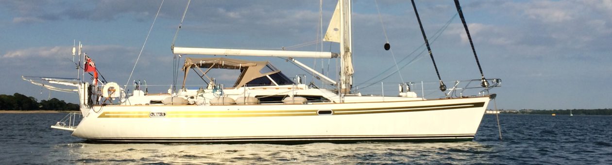
Mariadz, as a Moody 54, doesn’t have exceptional freeboard for her size but it is still well over a metre to the water line and nearly a metre from a floating pontoon to the deck. Maria and I are a little vertically challenged too, which meant when I snapped my Achilles Tendon or tore Cruciate ligaments, it was tricky to get on board – in the end you have to sit on the rail and swing your legs round.
But do we need this? At the moment we have a throne on the pontoon. This is a huge wooden staircase to the boat that works really well but will be left when we start our travelling. So potentially we would need something for when we are travelling and Maria had taken a shine to this video when it came out. Surely I can work something out and put it together for less than that!
 I have been fortunate to have Pete and Linda as neighbours
 for the last two years and one of the things I have noticed as they fit out the beautiful Haven Voyager is that Pete designs a lot in cardboard before making it or buying it. This gave me the inspiration to mock up the steps prior to buying any wood or hinges! I can also thank my son Matthew for drinking the cider that made this all possible.
The model worked really well from the wood perspective but didn’t give me a great view of the problems I was likely to have with hinges. You need two types of hinge for this design a flush fitting hinge which helps with anything that goes out to 90 degrees and a butt hinge for joints that go out to 180 degrees.
So, here he we have the Mariadz designed Magic Pontoon Steps (patent pending 😉 ),
{drum roll please}


So what do you need to make these fine pieces of modern design?
The measurements below are based on producing steps that are 60cm tall (Height) with a first step at 30cm. The depth (thickness) of the wood is key and I have assumed 12mm (woodwidth) but will also explain below how the sizes are made up so that people can adjust as necessary. Dimensions are Length x width and all measurements and I have rounded up the woodwidth to 15mm for calculations for ease of cutting and also because this gives a little space which the hinges are likely to require anyway.
Wood – (B&Q do a fantastic cut to size service which is very accurate)
- The back – 60cm x 60cm [(Height) x (height)]
- The concertina sides (4) – 60cm x 28.5cm [(Height) x (Height/2 – woodwidth)]
- the top 1 – 60cm x 10cm [(height) x (width*7 + a bit?)] – the width is what provides the top part that closes the pack and so you want to be too much rather than too little.
- the top 2 – 60cm x 50cm [(height) x (height – top 1 width)] – best that the top is cut from the same sheet
- Steps (3) – 30cm x 60cm [(height/2) x height)]
- small step sides (2) – 30cm x 30cm [(height/2) x (height/2)]
- top bars (2) – 45cm x 45 cm [(height – top 1 width – wood width*4) x (height – top 1 width – wood width*4)]
hardware – (I chose 50mm brass hinges)
- 10 Butt hinges
- 14 flush hinges
- 12mm screws (100) – check that the hinges don’t come up with 16mm screws, or you are through the wood!
- 16mm “ish” screws (6) – these need to be less than (2*wood width)
- magnetic catches (2)
- anti slip tape
Considerations/Steps
 There are basically three types of joint in the design. The outside of the box
  requires a joint that forms an L so that the top of the box is supported on all sides for stability. This means that the flush hinges need to be brought in by the width of the wood and recessed into the wood to provide a flush finish (I would now recess these differently to the picture with the larger part of the hinge being recessed but I did the first as in the picture and wanted to stay consistent at least on the inside of the box). Two of the concertina sides are joined to each side of the back using this method and the other two are joined to the top step in the same way, I used two hinges for each joint irrespective of size. Having built the U of the back and two sides and the same U shape for the front, we can join these together with the butt hinges. You now have a box with one end which is only half covered and has the front of the top step. We can now fit the top step itself, which is the top of the box, by fitting two flush hinges onto the top edge of the back on the outside and then the smaller top piece can be fixed. The larger top piece is then attached to the smaller with two butt hinges (on the inside). Our top step is taking shape. Now to avoid any unfortunate accidents it is a good idea to attach two bars on the underside of the longer part of the top step. These will stop the concertina collapsing inwards. They should be mounted a wood width from the outside edge and have at least a wood width on the outside edge at the front.
Now to do the bottom step. We already have the facing for the top step on the box so we need to make an L shape with our two remaining step pieces of wood using flush hinges and again positioning the hinge so that it forms an L when opened. Now we can join this L to the bottom edge of the top step which forms part of the box, , using the flush hinges, which should allow the entire step area to fold up to the top of the box. The next step is to attach the small step sides to the bottom of the box under the steps so that they fold in and then come out under the steps. In order to ensure that the bottom step sides stay in place, I used magnets on the inside of the small side pieces to lock it into the back of the bottom step. My steps are untreated so far but the plan is to get this done too since they will be outside a lot of the time.
Finally, put anti-slip tape over the steps and top, we don’t want any accidents. At the end, you should get the following..
You can see the video was done before the protection or anti-slip was applied, I’m just a little premature I guess….. A month later, I have used International Paints Woodskin to waterproof and protect the wood, Anti Slip Strips
to stop any accidents and the boat name in gold, which isn’t too clear with the wood colour unfortunately. The final element is a weathermax bag for it to go in, and I’ll probably throw some silicon sachets in there.
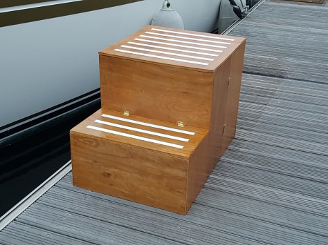
So the steps are done. The size works well for us since we have 90cm above the pontoon to the deck and it means three same sized steps and you are on board, probably useful that they are all the same size in case someone isn’t concentrating. As an alternative and nearer to the example from the original video, the steps could have been a little smaller, since the overall dimensions of these steps are 60cm x 60 cm x 12cm. It is quite easy to have the height at 40cm or 50cm, and hopefully the explanations above will help to explain how to do that.
So now for the unbelievable offer. So anyone seeing the original video of the deck box will know it costs $3,000 (but it is a beautiful piece of art, the Rolls Royce of deck boxes). I would be happy to make the Magic Pontoon Steps to the quality you have seen in the videos, to an agreed, realistic size, for £300 + delivery (feel free to email us at mariadz@mariadz.com). I know, I know, I am robbing myself. Clearly Maria’s special steps cost four times this, they are a present after all! For those who prefer to go it alone, I hope my instructions above help.

 In just over an hour we are tied up to a mooring buoy, the Prosseco has been broken out and the girls are starting to relax. We settle down to watch the sunset over the River Orwell as our pork chops cook in the galley. At the age of 72, Adam’s Dad has discovered Facebook. His regular posts on the recovery of Adam’s Mum from a stroke in March, help us all understand the progress and the difficulty of these long term recoveries. It is clear from his latest update that today has been a hard day and we agree to facetime him to have a face-to-face chat over the internet. Two hours later, dinner has been switched off, alcohol has been consumed and we are all still chatting but Dad is in a better place and his favourite daughter outlaw (in joke I’m afraid) is now past eating. A few more drinks and a bit more chatting and it is time for bed before we head to Osea Island the next day – I never get my own way 🙂
 This is the Ross Revenge which is the boat that used to broadcast Radio Caroline in the North Sea during the Eighties. This was after the first Radio Caroline ship, Mi Amigo, had sunk which is remarkably similar to the story for the “The Boat That Rocked”, although apparently this is a coincidence! So a little bit of history to enjoy as you sail past. There are then a large number of moored boats before you get to the anchorage at Osea Island. We arrive shortly before 6pm, right on low water, and with only five other boats spread around the anchorage find a good spot and start to drop anchor. In one respect arriving at low water has the advantage of simplifying the calculations for the anchor chain although it does mean that we did not benefit from the tide at any stage!
 although on this occasion I forget to attach the anchor ball to the anchor to help with
  location and retrieval in an emergency. Time to relax again, as the sun goes down and out comes the Prosecco and the raspberry gin – hmmm, theme developing here. Our friends are at Brightlingsea listening to music and send us a video, the singing doesn’t sound the best if we’re honest and doesn’t compare to the band we can hear on Osea Island where there must be a wedding
  or large summer party. It’s a lovely, still, warm evening as we settle down. For the second night, the fishing rods are shut firmly in their carrier and my Dad FaceTimes us and we talk for ages and Bonnie chills on deck.
 Maria has taught him to do a high five for treats, he likes to practice this a lot and he has the girls wrapped around his little paw! He gets treats.
 Clyde is now being a bit cheeky and trying his “come to bed” eyes on Lisa!
 they are falling behind as we start to catch up with a couple of smaller boats ahead of us. We travel up the wallet passing Walton, Frinton and Clacton which all look very different from the sea.
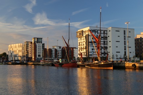

 Maria was going to be busy working so I asked Phil and the team to take Mariadz out of her berth which was done professionally and carefully. As she came out, there were quite a few barnacles and weed on her. We also checked the prop since we had quite a bit of vibration from the prop which you could hear in the aft stateroom when under power. There were a number of barnacles on the prop which could have caused the blades to not fully deploy and hence result in vibration, so the servicing of the prop is very important and something we need to check after its service. As part of the lift out service, Mariadz is pressure washed which cleans nearly everything off the hull and then she is put in her place for the next three weeks, as we move onto the motorhome.
 through hull replacement and Terry and Ben get started on this first. We quickly find that the hope that we would be able to keep some through hulls or even salvage some of the existing ones. Very quickly this became a pipe dream, as the through hulls started to come out.
  Some of them were wobbling in place, some were becoming pink inside (a definite sign that they need changing) and some of the valves would not close properly which of course is a big issue if you needed to close these in an emergency.
  The replacement goes really well despite some access issues and all of the through hulls are now changed. The two in the galley which also acted as keel coolers for the refrigeration are replaced with standard large through hulls and the keel coolers are moved slightly. These are changed from the vented coils to two porous blocks, with their own anodes, that soak up the water and cool the fridges. Apparently this is a new
  design which cannot be blocked by weeds etc. so we are hopeful that our fridge and freezer issues are finally solved for the last time. Also with the removal of the temporary fan solution, the noise in the galley has also reduced. The rekeying of the coppercoat is done with a light sandpaper after I have gone round and removed the last remnants of any barnacles on the hull. The hull anode which was replaced earlier in the year was also reasonably worn, but with some life left in it, but we decided to change this at the same time. The hull had been well polished and is looking fantastic.
 our berth we need to check for leaks and that the through hulls are seated correctly. Terry is on board and checks all of the through hulls. As he comes back on deck, he is pleased that out of nineteen through hulls, none of them leak. I’m not sure I’m 100% happy with the hint of surprise in his voice….only joking, they have done a fantastic, meticulous job and it is not surprising at all. We have some minor problems with the old pipes connecting to the new through hulls but these are all addressed and there is no water coming into the boat. Interestingly, we were told that when the one through hull was done earlier in the year, the boat had to be relifted because the new one leaked which makes us even happier with our decision to use Terry!
 To be fair, it was pretty much the only thing that worked as it should when we got the boat 🙂
 the smell was more pronounced. Oh dear, this is going to be nasty. Inspection around the holding tank showed that there was no leak, that was a relief. We also knew that the holding tank was empty since we had emptied it a few weeks ago. Over the last few years we had changed a lot of the pipes, hence the white pipes in the picture. The creamy coloured pipes are the remaining pipes but these appeared to be fine with no smell coming from them. We decide to try and trace where any gas is escaping the system by putting a fairy liquid solution across each of the pipes and around the top of the holding tank. This reveals that the “gas” is escaping from around the sender unit that shows whether the tank is full or not. It also revealed a small split in the pipe that led to the sea discharge, maybe this was enough to let the smell out? Rather than replacing the new and clean pipe we decided to put in a join and replace the split part with a new short length of pipe. This was uneventful, having heated the new pipe in a pan of hot water for a couple of minutes to ensure that the 38mm pipe went onto the 40mm fitting on the holding tank…. a snug fit! But we were not convinced that this constituted the full extent of the problem. We then decided to add some water to the tank and discovered that the tank was under pressure when I opened the pump out and heard air hissing. The setup on the Moody has two inputs from the two toilets, a deck pump out, a sea discharge and finally a breather pipe. With a breather pipe which works both ways, there should not be any pressure. This led us to do some investigation on the breather pipe to try and understand why there is pressure. Firstly we wanted to check that the breather pipe in the holding tank didn’t have a long downpipe (I.e. That the breather wasn’t connected to the pump out by mistake. Having checked which pipe was which and removed the tank inspection panel, it was time to hold your breath and open every window on the boat! That is definitely the smell…. but the pipes are the right way round – quick put it all back together again! Consulting the owner’s manual revealed where the breather pipe left the boat and it was interesting to see that this was a smaller pipe than the inch and a half pipe leaving the tank. A reducer somewhere perhaps? It also appeared that there was a join with another breather pipe…very confusing. The breather pipe goes forward and we can see it doesn’t come back at hull level, so maybe The return is high and is in the headlining? Removing fifteen screws allowed us to check that this wasn’t the case! Great now to put them all back again. But we are still confused as to how the breather is working. We decided to force air into the breather using a footpump from the tender. There was a bubbling coming from the sink! The grey water system linked to the black water system for a breather??? Surely we would get foul smells from the sinks.
  Tracing back the pipes revealed that the join in the breather pipes was from both grey water boxes and wasn’t linked to the black water breather at all. Back to the manual….and tracing the breather pipe forward behind the TV and up further forward. Check the hull to find a second breather, so the manual is incorrect and the pipe runs further forward. Ps, this breather isn’t the fuel breather which is adjacent to the fuel cap or the fresh water system breathers which are in the cockpit…
 Some of these had clearly never been recessed, and so we wanted to cover these with teak plugs. I had borrowed a drill bit that was 10mm wide with an extended central point that makes the hole in the fibreglass under the teak but I was keen not to drill down too deep and was concerned that I wouldn’t have enough teak to hold the screw and allow me to cover it with a teak plug.


 washing machine which is small and apparently designed for the yachting life. However, Maria wanted to see if there was a portable solution that would work on the boat, in the motorhome or in Italy before the main house was finished.
 she decided on a
  whether the

 Some of them do not have great access so someone with small hands is best. Firstly Houghton It is very important to completely empty the coolant before you start! We don’t want a messy bilge…. Each removed pipe is labelled so that we know what we have replaced and jubilee clips are replaced as required. As part of this work, various engine parts were cleaned up or replaced including the thermostat. By the end of this process we will have a pretty new engine 🙂 it takes quite a bit of time to do all of this work.
 I now get to see what I have to deal with… The entire mechanism is glued together with calcium, salt and lots of old grease which has hardened. The whole thing was solid and it is difficult to see how the thing moved in the first place.
 The bearings are equally bad with no movement. At this point I have to admit that the act of cleaning these things up and getting them back together is incredibly therapeutic and does give a great feeling of satisfaction when it is all back together again so thoroughly recommended. When I was young I used to try and fix broken alarm clocks. In common with a number of people I would take them apart and put them back together again, they never worked again and there were always a few spare parts lying around at the end of the process. It is important that this isn’t the case when rebuilding a winch! A nice way to try and stop this happening is to be very organised as the winch is taken apart.
  I laid out paper towel on the deck and had each group of parts on a single piece. I found this really helped to make sure that I put it back together in the same order as it came apart. As you can see, there was a lot of work required to clean these up and the whole process, with a few interruptions, takes a number of hours. There is no way I am getting the second one done on the same day.


 We had found that a bolt had sheered which held the casing of the alternator together. This had come out and had significantly damaged the vanes of the fan, which also explained the noise Maria heard. So we get the alternator off and I will take it to the local specialist to see what can be done. On investigation the alternator is fried and badly damaged which makes it uneconomical to repair. A replacement is available and should be with us within 24 hours.
 There is a problem, it appears the bolt holding the engine earth to the negative bar is loose (right hand side of picture). This has caused arcing between the cabling and therefore heat build up with some scorching. In fact one of the negatives has corroded and melted the insulation so much that it has melted through another wires insulation and these are welded together. That will be what caused our problems and it could even have been what damaged our alternator. In some respects we were probably lucky the alternator went rather than continuing to build the heat up and potentially start a fire under the bed. This doesn’t explain why the old alternator used to provide the earth to the engine and the new alternator doesn’t, despite being identical. The current view is that this was as a result of the damage to the alternator which provided that earthing thereby by-passing the corroded engine earth. But I will update with more information as it is available.